omega-48-72-96 channels ERT SYSTEM


GEOTECH ERP-1 1D Vertical Electrical Sounding and Profiling Equipment
RESISTIVITY SYSTEM OMEGA-48
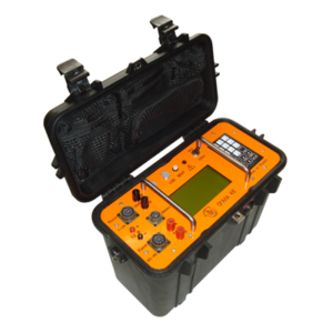
OMEGA-48 is a multichannel Resistivity system designed for vertical electrical sounding (VES) and induced polarization (IP) methods on electrical resistivity tomography (ERT) technology.
OMEGA-48 is a multichannel Resistivity system designed for vertical electrical sounding (VES) and induced polarization (IP) methods on electrical resistivity tomography (ERT) technology.
Resistivity system OMEGA-48 consists of
•Multi-electrode 10-channel Resistivity instrument which includes transmitter, receiver and switching unit connected to current and measuring lines in a single heavy duty cable with waterproof enclosure
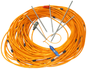
•Two sections of multi-core cable with 24 electrode each
•Industrial laptop
•Software for system control, results acquisition, data processing and interpretation:
•developing field measuring protocol, SEQ files,
•managing measuring process, data collection and storage,
•visualization and editing field data,
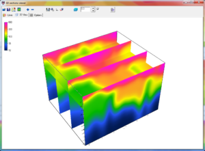
•automatic data 2D inversion,
•visualization of inversion result.
Resistivity instrument measures amplitude parameters of output current of the transmitter, electrical potential difference between measuring electrodes (apparent resistivity), time parameters of chargeability (apparent chargeability) determined on voltage decay curve at measuring electrodes after switching off the current.
RESISTIVITY SYSTEM OMEGA-48
OMEGA-48 is a multichannel Resistivity system designed for vertical electrical sounding (VES) and induced polarization (IP) methods on electrical resistivity tomography (ERT) technology.
Resistivity instrument measures amplitude parameters of output current of the transmitter, electrical potential difference between measuring electrodes (apparent resistivity), time parameters of chargeability (apparent chargeability) determined on voltage decay curve at measuring electrodes after switching off the current:
Specifications
| Number of measuring and current electrodes connected to the multi-core cable | 48, the multi-core cable consist of two sections, 24 electrodes each, the unit is located in the center |
| Number of channels for simultaneous measuring operation | 1 to 10. A pair of receiving electrodes for each channel is selected according to protocol |
| Number of current lines in simultaneous operation | 1. Transmitting electrodes pair is selected according to protocol |
| Electrode spacing | 1 to 10 m |
| Multi-core cable lenght | 50 to 500 m (two sections with length from 25 to 250 m) |
| Signal form | direct current bipolar impulses of regulated duration with pauses |
| Power supply | 24 V, external |
| Operating temperature | -20 to +50°C (option down to -40°C) |
| Transmitter | |
| Number of input channels | 1 (or 2 lines) (commutation multi-core cable is possible) |
| Direct current bipolar impulses of regulated duration with pauses | |
| Impulses duration | 0.2048, 0.4096, 0.8192, 1.6384, 3.2768, 6.5536, 13.1072, 26.2144, 52.4288 seconds |
| Duty ratio | 0.2 .. 0.5 |
| Output voltage | 30, 100, 300, 500 V |
| Instability of output voltage under variation of load resistance | 1% at most |
| Output current | 10 mA to 5A |
| Maximum output capacity | 0.5 kW (500 V – 1 A, 100 V – 2 A, 30 V – 5 A) |
| Time for complete current cut-off on active load | 10 μs at most |
| Protection from short circuits on the output | |
| Receiver | |
| Number of input channels | 1 to 10 pairs of dipoles |
| Input resistance of each channel | at least 20 MOhm |
| Range of measured signals | 10 μV to 12 V |
| Amplitude response of each channel | at least 2 to 3 μV |
| Instant dynamic range | at least 90 dB |
| Voltage of in phase signal on the input | 12.5 V at most |
| Amplification rate of the prime amplifier | 1, 10, 100, 1000 |
| Bit length of Sigma-delta analog-digital converter (ADC) | 24 |
| Level of in phase interference suppression | at least 80 dB |
| level of industrial interference suppression with frequencies 45 to 55 and 55 to 65 Hz | at least 80 db |
| Operating temperature | from -20 to +50°C (option down to -40°C) |


