Description
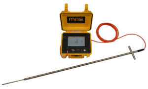
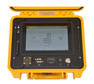
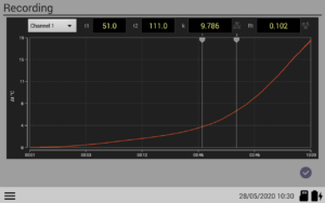
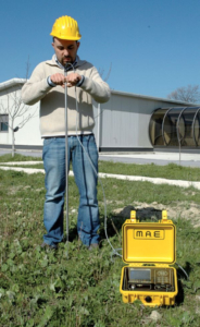
TCR24 is designed to measure soil heat transmission (soil tendency to transmit heat). This type of survey is usually carried out prior to install underground pipes, or prior to build geo-thermic wells to detect heat from the soil, for buildings heating or conditioning. Measurement can be done on site with the probe supplied, up to a depth of 120 cm, or in case of greater depths, it is possible to pick up samples of compact ground (logs) and perform measurement in laboratory with proper laboratory probe. Acquired data can be examined directly on site, at the end of the acquisition phase regulated automatically by the device and it is expressed graphically and numerically in watt / (metres x kelvin) where: watt = unit of power; metre = unit of distance; kelvin = unit of temperature. Operatively speaking, a hole is made into the ground using common drill (not supplied) and a perforation point of 20 mm diameter with prolonged rod (supplied). Then the probe is introduced into the hole and by pressing slightly, probe tip is fixed into the ground at about 20 cm, in order to obtain best coupling with soil. Data acquisition is initiated by pressing a button, it is managed automatically by the instrument and lasts few seconds. Numeric and graphic data is stored on SD memory and then elaborated with dedicated TCreader software supplied together with instrument.
Heat transmission of some types of soils
– Dry loose rocks: +/- 1.5 W/m K
– Gravel, sand, water table: 1.8 2.4W/m K
– Granite: 3.4W/m K
Methodologies
GROUND THERMAL CONDUCTIVITY
The measurement method is based on the so called unstable sensor technique, that uses a probe (also called thermal needle), which mounts a heating wire and a temperature sensor. The probe is introduced in the ground. From its response when subject to a heating cycle for a few minutes, it is possible to calculate the thermal resistivity (or its opposite, the heat transmission).
The principle of the measurement is based on a peculiar characteristic of a rectilinear heat course (the heating wire of the probe): after a short transitional period, the increase of the temperature depends only on the heating power and heat transmission of the medium. Once the first is known, the second can be calculated. The main applications of the technique consists in the testing of high voltage cables and heating ducts.
Technical Specifications
General
CPU: ARM Cortex A9
Power supply: Li-ion 10,8V/12,4Ah
Autonomy: > 8 hours
Acquisition medium power consumption: 350mA
CPU environmental conditions: Temperature (°C):-20 a 70; Humidity (RH): 0-90%
Monitor: TFT-LCD capacitive 7” touch-screen, 1280×800
Connections: USB
Data storage: Internal memory 5 GB (up to 300.000 acquisitions) / external USB
Case: Polypropilene, automatic pressure valve, IP67
Dimensions: cm 27 x 24,8 x 12,3
Weight: 3 kg
Reference regulations: IEEE-442-2017 ; ASTM D5334–14
Acquisition
Type of measure: Resistivity and thermal conductivity
Number of channels: 2
ADC converter resolution: 24 bit
Measurement range Thermal conductivity: from 0,1 to 6 W/m*K
Measurement range Thermal resistivity: from 0,17 to 10 m*K/W
Accuracy: +/- 6%
Measure interval: 300s – 900 s
Temporal measure resolution: 25 ms
Standard probe total length (CTS120): 120 cm
Needle length (CTS120): 17 cm
Probe diameter: 6,3 mm
Probe environmental conditions: 0°C / 50°C
